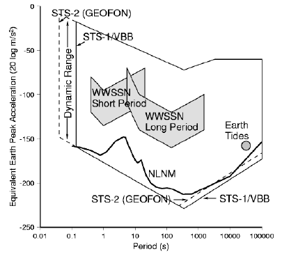
The longer the periods of ground motion to be recorded, the larger is the potential influence of environmental disturbances, such as temperature and air pressure fluctuations, induced ground tilts, etc. on the seismic recording and the larger the need for effective shielding against these. The instrument with the currently best very long period resolution is the Wielandt-Streckeisen STS-1/VBB (Wielandt and Streckeisen, 1982, Wielandt and Steim, 1986). It is most widely deployed in the IRIS GSN and GEOSCOPE global networks as well as in some regional networks (e.g. MedNet). In the permanent GEOFON network, mostly Wielandt-Streckeisen STS-2 and a few STS-1/VBB instruments are used with comparably good results. Fig. 1 shows the resolution of the STS-1/VBB and the STS-2 in relation to the New Low Noise Model by Peterson (1993). As compared to the STS-1/VBB, the more compact, lighter and cheaper triaxial STS-2 has a pass band with a slightly larger low-frequency corner (0.00833 Hz instead of 0.00278) and a significantlly larger high-frequency corner (dashed lines in Fig. 1). Depending on the properties of the recording system, 50 Hz (instead of 10 Hz) can easily be reached. The maximum long period resolution can only be achieved when the seismometers are properly shielded. There are other BB instruments too, e.g. the widely used GURALP CMG 3-T. But because of their significantly lower ratio NLNM/self noise for long periods they are less suited for permanent global or regional stations.

Fig. 1: A representation of the bandwidth and dynamic range of a conventional analog (WWSSN short and long period) and digital broadband seismographs (STS-1/VBB and STS-2 with GEOFON shielding, respectively). The lower bound depicted is determined by the instrument noise. The scale is in decibels (dB) relative to 1 m/s**2. Noise is measured in a constant relative bandwidth of 1/3 octave and represented by "average peak" amplitudes equal to 1.253 times the rms amplitude. NLMN is the global New Low Noise Model according to Peterson (1993).Thesis: For nearly all except a very few sites on earth a properly installed STS-2 seismometer will give nearly the same performance as a set of STS-1/VBB seismometers.
The following discussion of the shielding efficiency at GEOFON stations in surface or shallow depth vaults or tunnels in the next chapter is only based on the VLP channel plots (sampling frequency 0.1 sps) of STS-1 records (original or simulated from STS-2 records). The low self noise of the STS-2 allows us to simulate with good quality STS-1/VBB records up to tidal periods. Therefore a direct visual comparison of STS-1 and STS-2 recordings at the different sites is easy.
Question: Can you tell which tidal wave recording in Fig. 2 is recorded by an STS-1/VBB and which one is obtained from an STS-2?
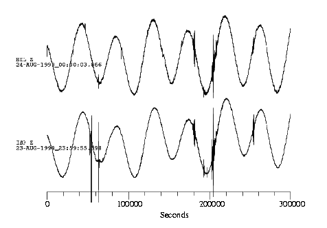
Fig. 2: Tidal recordings of STS-1/VBB and STS-2 do not differ very much when properly installed in a comparable environment. The two traces were recorded in the Eastern Mediterranean in buried vaults in limestone. At the station EIL (Eilat, Israel) an STS-2 with additional GEOFON shielding and at ISP (Isparta, Turkey) a set of STS-1/VBB are installed. See also the zoomed traces for more detailed comparison (click here).
Installation of an STS-1/VBBDetails on EIL Details on ISP
Seismometers must be shielded against environmental influences, namely pressure and temperature variations as well as magnetic disturbances. The proper installation of an STS-2 to achieve good VLP performance is discussed rather detailed in the next paragraph. Related comments on the STS-1/VBB are kept short here since this is a well known procedure and described elsewhere (Wielandt and Streckeisen, 1982, Holcomb and Hutt, 1992).
The three separate STS-1/VBB components are supplied with different shieldings: a permalloy helmet as magnetic shield (vertical only), an aluminum helmet and a glass bell jar for evacuation. The feedback electronics are placed in a separate container. There are two basic methods used for the installation of STS-1/VBB seismometers. The "conventional" one, also suggested by the manufacturer, uses a plane glass plate which has to be cemented to a plane pier (photo). The second one, introduced by the Albuquerque Seismological Lab, uses a warpless rigid stainless steel base plate (similar to the the aluminum one used in the GEOFON STS-2 shielding) on which the vacuum glass bells and the metal helmets are installed above the actual seismometer (photo).. The second method is faster and easier to perform and gives some more flexibility (see e.g. a detailed ASL report for more details: Holcomb and Hutt, 1992).
The STS-2 does not come with any shielding. All three identical triaxial components and the electronics are placed in a single casing. Magnetic and pressure shielding is already achieved by this casing to some extent. Nevertheless, temperature shielding is still an important issue to obtain longer period signals with a good signal/noise ratio above 20 sec especially because of the thermal convection generated by heat from the electronics. A rather sophisticated shielding (Fig. 3 a) was introduced by Wielandt (1990) for the first STS-2 based network, the German Regional Seismograph Network (GRSN). The STS-2 is installed on a 10-cm thick gabbro plate covered by an airtight aluminum helmet. Before being covered, the STS-2 is insulated with a thermal blanket.
For the GEOFON stations a simpler and more handy approach is used (Fig. 3 b). It is basically an aluminum casing consisting of a rigid thick base plate (3 cm) and a thinner aluminum helmet with a cylindrical foam rubber insert (photo) . As in the case of the gabbro plate, this base plate cannot easily be bent by the influence of pressure variations and gives, together with the foam rubber insert, extra thermal stability. In addition, this shielding serves as a corrosion protection measure and is separated from the pier or ground surface by adjustable tripod screws.
The GRSN shielding has an extra internal cabling
and a socket outside while the original STS-2 cable is penetrating the GEOFON
aluminum casing through a special hole which is made tight with silicon. The
advantage of better electrical performance of the GEOFON shielding without extra
connectors/sockets is decreased by not as perfect pressure integrity. The GEOFON
shielding is still portable and easily commercially available while these are
problems with regard to the GRSN shielding. For detailed comparison and photos
click
here.

Fig. 3: GRSN (a) (figure after Wielandt, 2000) and GEOFON type (b) shieldings for the STS-2.Figure 4 shows the substantial LP and VLP noise reduction which can be achieved even by an incomplete GEOFON type shielding (aluminum casing only, no polystyrol box!) in the period range above 30 sec up to more than 10,000 seconds. The major effect of about two orders of magnitude in terms of spectral power (one order of magnitude in terms of amplitude) can clearly be seen between 100 and several thousands of seconds and again around 10,000 sec. The GRSN shielding gives in most cases exactly the same picture. Just in very rare situations - probably in connection with large air pressure variations - the performance of Wielandt's approach in the range of several hundreds of seconds is slightly better.
For even better thermal insulation both types of installation methods can be complemented by covering them with an additional styrofoam box completely filled with styrofoam beads (see Fig. 3b and a photo).). The box should be tightly glued to the pier or ground surface and also the box lid to the box walls after filling with styrofoam beads. Depending on the site conditions, this box can give up to another order of magnitude in VLP noise reduction.
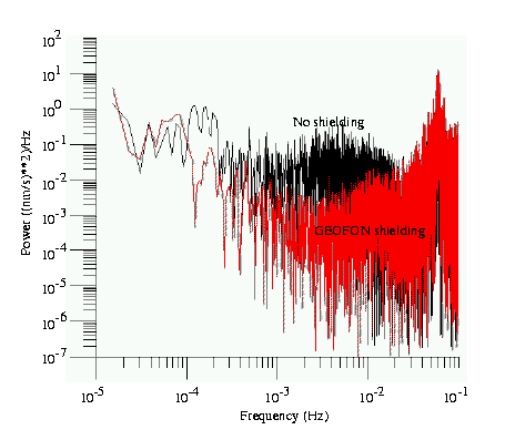
Fig. 4: Shown is the VLP noise reduction achieved by using the simpler version of the GEOFON shielding method (no addtional polystyrol box and beads ). The relative noise power spectra of the vertical component of two STS-2 standing side-by-side are displayed here. No instrument correction has been applied. The black spectrum is from the unshielded STS-2, the red one from the shielded one. To see the original traces, click here.

Fig. 5: Sketch of an artificial horizontal tunnel construction with different chambers to host a VBB seismological station. This type of construction is widely used within the IRIS/USGS part of the IRIS GSN network. The total length of the tunnel is approximately 25 m. The pure construction cost of such a vault can reach up to 100,000 US$ depending on the local conditions and infrastructure.Figure 5 shows a sketch of an artificial tunnel vault which is used at several IRIS/USGS installations in cases where no other existing underground facility can be used. The tunnel is about 25 m long and segmented by four doors (air locks). The last chamber contains the large seismometer pier. Since the tunnels are drilled into mountain slopes, the vertical coverage is in the order of the tunnel length or higher. Although the vault construction is identical, the VLP performance at two different sites is not. This is shown by the tidal recordings in Fig. 6. The tunnel of the IRIS/GEOFON station LVC (Limon Verde, Chile) is built in hard basaltic rock and the traces show a remarkably low VLP noise, while at KMBO (Kilima Mbogo, Kenya, also an IRIS/GEOFON site) a soft volcanic conglomerate drastically increases the noises, especially on the horizontal components. Another effect which can cleary be seen on the horizontals is the large day-night time noise variance. General day time temperature increase and maybe also the deformation of surface rocks caused by the direct sunshine during the day and stronger blowing winds causes the substantially increased VLP noise levels on the horizontals at both sites. So even this kind of very sophisticated and expensive tunnel vault construction gives no guarantee for seismic recordings free of environmental influences. This is verified below in Fig. 6 where the strong effects of both adverse geological underground condition (KMBO) and of day-to-night temperature variation on the VLP noise on the horizontal components can clearly be seen.
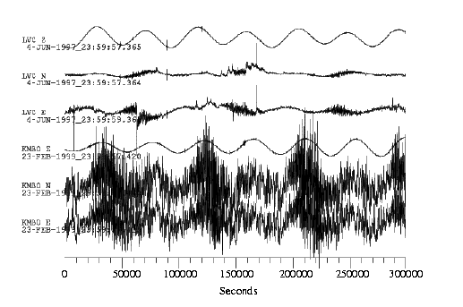
Fig. 6: Comparison of two 3-component STS-1 VLP traces recorded in identical tunnel constructions but in different geological and climatological environments. LVC (Limon Verde, Chile) is built in hard basaltic rock in a full desert environment, KMBO (Kilima Mbogo, Kenya) is placed in rather soft volcanic conglomerate influenced by mostly humid tropical environment. Day-to-night temperature gradients are high in both cases.
If tunnel vaults are not affordable, other less expensive methods of getting the seismometers sufficiently buried have to be used. Several cases are discussed in the following.
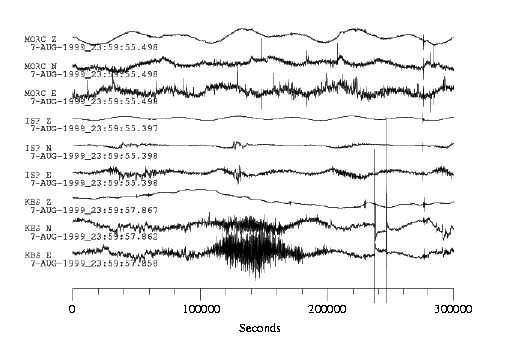
Fig. 7: Comparison of three 3-component VLP records in rather shallow vaults (4 - 5 m). At MORC (Moravsky Beroun, Czech Republic) an STS-2 is installed in a 1 m wide borehole in hard rock, in ISP (Isparta, Turkey) and KBS (Ny Alesund, Spitsbergen) the sets of STS-1/VBB are installed in an underground bunker vault in limestone and weathered rock (permafrost), respectively.Figure 7 compares the recordings made at three different stations. The depth of burial is only about 4-5 m in all cases. Compared to the tunnel vaults this is a very poor depth of burial. Nevertheless, the moderate climate especially in case of MORC (Moravsky Beroun, Czech Republic) but also at ISP (Isparta, Turkey) gives a relatively good VLP performance. These vaults are build in hard rock and limestone, respectively. The spikes which can be seen mostly on the horizontal traces are due to human activities close to the site. In the arctic climate of KBS (Ny Alesund, Spitsbergen) a more drastic temperature change causes an increased VLP noise level on the horizontals. Also here some spikes caused by local man-made disturbances can be observed.
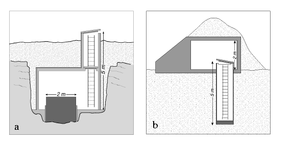
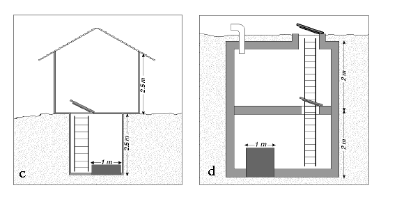
Fig. 8: a) Underground bunker vault construction for the installation of a set of STS-1/VBB (remote recording). b) "Wide & shallow borehole" vault construction for the installation of an STS-2. c) and d) Simple bunker vault construction schemes for an STS-2. The vault constructions b - d allow onsite data recording due to the existence of a separate recording room.The vault constructions at KBS and ISP are very similar: about 5 m deep large underground concrete bunkers with large concrete piers for the installation of the STS-1/VBB seismometers (Fig. 8 a). The geology is weathered rock in permafrost (KBS) and limestone (ISP). The recording systems at KBS are located somewhere else while at ISP the recording is done locally in a house built above the vault. At MORC, a simple borehole construction has been made: a very wide shallow vertical borehole has been drilled into hard rock and a one meter wide steel tube placed into it, with a concrete floor on the bottom. On this, the STS-2 in GEOFON shielding has been installed at about 5 m depth (Fig.8 b). Here and in the two other examples of construction schemes for STS-2 stations (Fig. 8 c and d) a recording room hosting all computer and communication equipment is available above the seismometer vault.
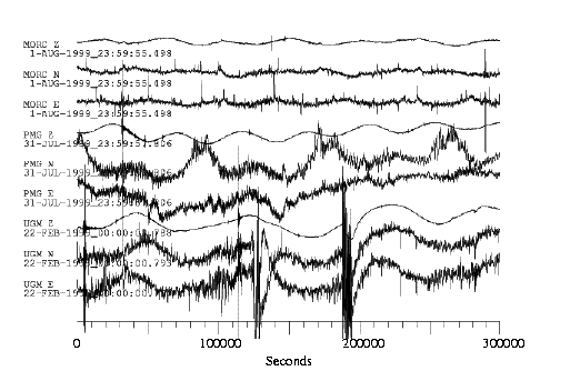
Fig. 9: Comparison of three 3-component VLP records from shallow vaults in rock in different climates. Data from two sites close to the equator (Port Moresby, Papua New Guinea, PMG, and Wanagama, Indonesia, UGM) are shown together with data from MORC (same station as in Fig. 7).Figure 9 shows, again in comparison to MORC, the recordings of shallow vaults in locations near the equator. At PMG (Port Moresby, Papua New Guinea) a two room underground vault hosts a set of STS-1/VBB seismometers. The two room construction situated in a sedimentary layer above rock is comparable in size with the one at KBS and ISP, but even more shallow (3 m) and with a horizontal entrance into the first (the recording) room. At UGM (University Gadja Mada, Wanagama, Indonesia) a very simple, also only 2.5 meter deep bunker in limestone (construction after Fig. 8 c) hosting an STS-2 with a small open recording hut above, shows rather similar results especially on the horizontals. The extreme large amplitudes at UGM at day time are caused by human activities close to the station. In principle, the VLP station performance is not so different at both equatorial sites and especially the horizontal traces are not as good as at the site in a more moderate climate. The instrumentation and construction details do not play any role for the resulting VLP performance.
Surface Vaults in Moderate Climate
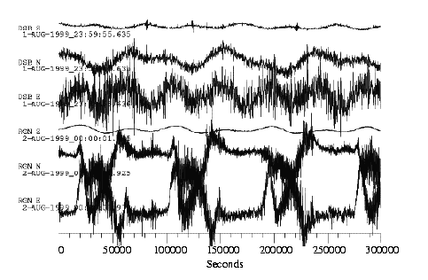
Fig. 10: Comparison of two surface vaults in moderate climate on rock and in sediments. At DSB (Dublin, Ireland), a small surface bunker was built in an old granite quarry. At RGN (Ruegen Island, Germany), an old one-room military bunker with a thin (< 1m) soil cover on top is used. Both sites host STS-2 seismometers with GEOFON shielding.The STS-2 records in Fig. 10 are obtained in a simple above-surface vault on rock (DSB) and a very shallow one in soft sediments (RGN). Both sites are located in an area with a very moderate climate and close to the sea. Temperature shielding is a little better at RGN due to complete soil coverage on three sides and up to one meter on top. Therefore the general VLP performance - as can be seen on the vertical components - is better here, but the horizontals show large additional distortions during day time. The latter are most likely caused by temperature induced swelling and related upbending of the sand hill which is a very typical behaviour for sediments (as can be seen partly also on the PMG records in Fig. 9). This is not the case on rock at DSB. It is remarkable that there is almost no day-night variance on the DSB records although the vault is completely above surface. This is due to the sea climate with very small day-night temparture changes.
Surface Vaults in Arctic Climate
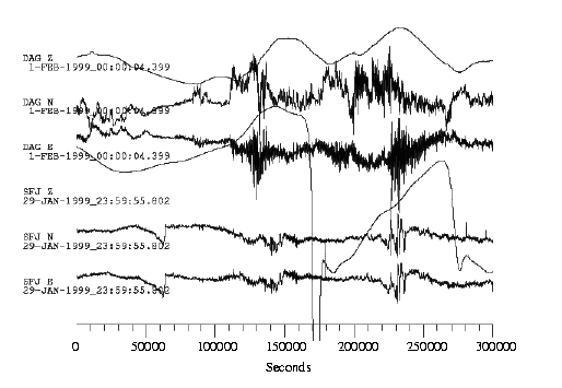
Fig. 11: VLP records obtained at two surface vaults on Greenland. At DAG (Danmarkshavn, NE Greenland) a STS-2 in GEOFON shielding is installed in a wooden hut on weathered rock close to the sea shore. At SFJ (Sondre Stromfjord, SW Greenland) a set of STS-1/VBB is located in a container like building on top of a mountain. Geology is also weathered rock in a permafrost environment.The very low VLP performance of surface stations in arctic climate can be seen in Fig. 11, where data from two stations on Greenland are shown. Both vaults are located in wooden huts built on weathered rock above surface, more or less open to all kinds of atmospheric turbulences in terms of air pressure and temperature changes. The vaults must be heated in winter. This results in about the worst conditions one can imagine for the VLP performance. Tidal waves are no longer seen very clearly and the daily noise variations are large. Nevertheless, in these regions there is no other choice. Especially DAG is in one of the most remote places on earth where it is almost impossible to build a better underground vault.
The VLP performance of a VBB seismological station
is directly dependent upon several instrumental and environmental parameters.
High quality VBB seismometers, a true 24-bit A/D converter and a continuous
multi-stream data recording are essential. In the GEOFON network, only STS-1/VBB
and STS-2 seismometers and Quanterra data loggers are used for this reason. With
appropriate shielding, the VLP performance of the STS-2 is not much different
from the STS-1/VBB. So only in very rare cases at extremly quiet sites, the
extra infrastructure, installation, maintenance and financial efforts related to
the usage of STS-1/VBB sensors can be justified. The same is true for the vault
construction. The construction scheme itself has not much influence on the
station performance as long as the depth of burial is deep enough and the
environmental disturbances can be reduced to a minimum. With an adequate casing,
a seismometer pier is not required to install an STS-2 sensor properly
underground. The geology plays a very important role. The harder the rock, the
lower is the VLP noise at a certain depth since surface tilts caused by
atmosheric influences do not penetrate as deep. Sediments show special tilting
effects which reduces drastically the day-time VLP performance of the horizontal
components. The shallower a vault is, the more influence has the general
climate. In very moderate climate, e.g. close to the sea, even surface vaults
can have a reasonable VLP noise level. Thus, although the task for
a VBB station to resolve the full seismic spectrum from high frequency
regional events to the very long period (VLP) part as far down as to the earth's
tides with sufficient dynamic range seems to be a very difficult and costly
effort, it can be achieved with rather simple means.
The author wishes to thank M.
Brunner for many exellent ideas and carrying out the shielding experiments and
K.-H. Jaeckel for a lot of fruitful discussions around this topic. The drawings
were made by E. Bauer and R. Stromeyer. The article was carefully reviewed by P.
Bormann and C. R. Hutt . Thanks to their comments it was significantly
improved.
Holcomb, G. L. and C. R. Hutt, 1992. An evaluation of installation methods for STS-1 seismometers. Open File Report 92-302, U. S. Geological Survey, Albuquerque, NM.
Peterson, J., 1993. Observations and modelling of background seismic noise. Open File Report 93-322, U. S. Geological Survey, Albuquerque, NM.
Wielandt, E., 1990. Personal communication.
Wielandt, E., 2000. Seismic Sensors and their Calibration. In: Bormann, P. (ed.): New IASPEI Manual of Seismological Practice, in preparation.
Wielandt, E. and G. Streckeisen, 1982. The
leaf-spring seismometer: Design and performance. BSSA, Vol. 72, No. 6,
2349-2367.